
Page 115 - The Indian Optician Digital Edition July-August 2021
P. 115
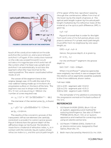
of the upper of the two rays shown passing
                                                              through the combination, differs from that of
                                                              the lower ray by the depth of groove, d.  The
                                                              optical path length is given by the actual path
                                                              length multiplied by the refractive index of the
                                                              material, so the optical path difference, OPD, is
                                                              given by
                                                                 n d - n d
                                                                       1
                                                                  2
                                                                 Figure 5 showed that in order for the light
                                                              from each zone of the full-period, phase zone
                                                              plate to arrive at P in phase, each path length
                                                              must differ from its neighbour by one wave
               FIGURE 9  GROOVE DEPTH OF THE KINOFORM
                                                              length, so
                                                                 OPD = n d - n d = λ.
                                                                         2
                                                                              1
          touch of the conductive material on the side           Hence, the groove depth, d, is given by
          switched the current on, and a second touch
          switched it off again. If the conductive material      d = λ / (n  - n )
                                                                         2
                                                                            1
          on the side was swiped forward it would                For the emPower  segment the groove
                                                                                  TM
          activate a microgyroscope which switched off        depth is
          the current when the head was upright and
          switched it on automatically, to activate the          550 / (1.67 - 1.53) = 3.93μm.
          segment when the head inclined to the                  When the emPower  adaptive spectacles
                                                                                     TM
          reading position. The wearer could select either    were originally launched, it was envisaged that
          mode at will.
                                                              the electro-active segments would be available
             The power of the segment lens in the             in the three additions, shown below.
          original design was +0.75 with the rest of the      Full near Adds
          near addition being made up in the form of a
          progressive surface on the back of the lens.  The   1.25 to 2.00 - segment add +0.50 D
          segment was oval in shape with diameter             2.25 to 2.75 - segment add +0.75 D
          20 x 12 mm and assuming λ = 550nm the               3.00 to 3.50 - segment add +1.00 D
          number of zones required was
                                                                 The remainder of the addition is provided by
                               2
             m = y  / 2 f ' λ = 10  / 2x1333.3x550x 10-6  =   68.2.  the progression worked on the back surface of
                    2
                  m
                                                              the lens.
             The diameter of the central zone, 2y , is found
                                                 0
          from                                                REFERENCES
             y  = √(2 f ' λ) = √(2x1333x550x 10-6 ) = 1.21mm.  1.  US Patent 6491391 (2000), Blum R.D. et
              0
                                                                  al. System, apparatus and method for
             so 2y  = 2.42mm.                                     reducing birefringence. See also US Patent
                  0
             The depths of the concentric grooves of the          7731358 (2010), Blum  R.D. et al. System,
          transparent diffractive element are carefully           apparatus and method for correcting vision
          controlled to provide the correct optical power.        using an electro-active lens.
          Figure 9 shows how the groove depth of the
          diffractive rings can be found. The kinoform,       2.  US Patent 7728949 (2010), Clarke R. et
                                                                  al. Electro-Active Lens. Assigned to Pixel
          made from a material of refractive index, n , is in     Optics, Roanoke, VA.
                                                     2
          contact with the nematic liquid crystal, whose
          refractive index is n , and the optical path length   3.  Both manufactured by Merck & Co. Inc. USA.
                             1

                                                                                               111 | LENS TALK